My dad and I got together on Saturday to do some
overdue maintenance on the TF. We contemplated a valve adjustment,
which led us to talking about how to do the valve adjustment, which
inevitably led to a discussion of designing a jig to do the
adjustment. Yes, I have feeler gauges and even a Click Adjust.
However, (and maybe it’s just my inexperience) it seems that my
valves are pretty fiddly to get right. We got to thinking that using
a dial indicator would be a good way to go. I checked the archives
and didn’t see anything about a jig, although I did find one
reference to a fellow who used one on an MGA with the indicator
mounted on a set of adjustable rods mounted on a head bolt. So,
fighting our tendency to over-complicate, I made the following jig
which is really very simple. I used it last night to adjust the
valves, and then because it was so easy to use, I checked the valves
again after a long drive.
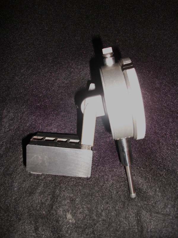
Here is the magnetic sled for the dial indicator.
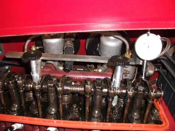
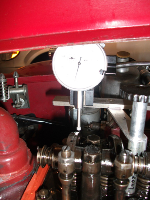
Here is the jig in use looking from the manifild
side. I put a post in the back of the sled that keeps it registered
to the right spot in the rocker.
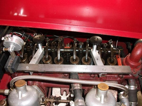
From adjustment side
From the adjustment side - wider picture.
insert content here
Ttalk.info
Jig for Adjusting Valves
by Scott Ashworth
It really is simple. I use the two threaded rods that hold the valve
cover to suspend a steel bar across the length of the engine above
the intake manifold. With ¼” pipe, I made two spacers that fit over
these rods. Because I did not want to remove the hood to do the job,
the front spacer is in two pieces, each of which fits the clearance
under the hood. Two short pieces of aluminum angle run from the rods
to suspend the steel bar. Above these pieces are two spacers that
run to within ¾” of the top of the rod so that I can use the knobs
from the valve cover to hold the thing in place. These pieces are in
the picture that I have attached to this post.
I made a sled for the dial indicator out of ceramic magnets, and put
an adjustment at the mounting point so that I could get an angle
that was close to that of the valve in the head. That will be in the
post #2.
What is nice is you can set the sled next to #8 valve to see when it
is fully open, then move it to #1 to set the gap, and then leave it
there to do the reverse. I really like being able to see the exact
amount of gap on the dial indicator. (You can go to the archives for
all the discussion you want about the right amount of gap, but I
used .012”.) The jig in use is in post #3.
It takes very little time to set-up, which is important because I am
slow as molasses and always lose the race to the cooling engine.
Isn’t it nice that MG provided us with a crank just to be able to
adjust valves?
Once again over-thinking a simple task…..
Safety? Fast?
Scott Ashworth – ’54 TF with 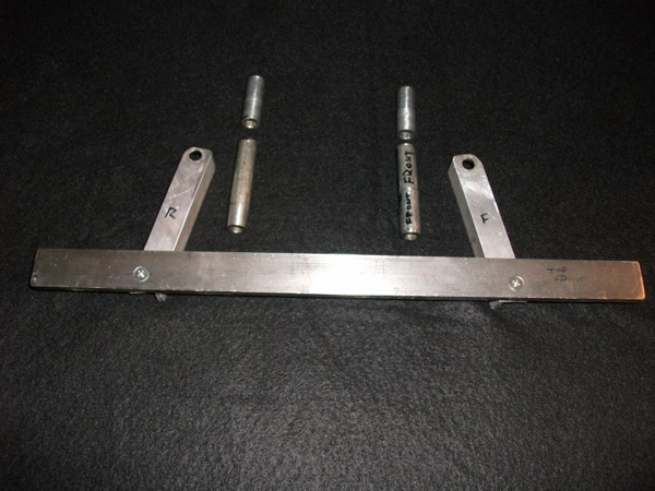
Good Luck.
Safety? Fast?
Scott Ashworth - '54 TF