In the above sketch, a new pedal shaft (22) was made with a control rod end on the pedal shaft lever . This mates to a U
(**) on the Clutch rod (37). A length of 3/4 inch drill rod was bored completely thru with the tap drill for UNF Fine 5/16 in. to
provide a greasing channel. Then 1/8 in holes were drilled at the three bearing locations (two body bushings and the
brake pedal bushing) and one end tapped for the grease fitting (as in the original pedal rod). A groove for a snap ring was
turned. The other end was also tapped for a 5/16 bolt. This bolt will hold a new pedal lever which was also made from drill
rod. This lever has a flat milled on one end and a corresponding step in the new pedal shaft, to provide a non turning fit
when the lever is bolted to the end of the pedal shaft. This lever is drilled and tapped to accept the control rod end. The
new pedal shaft is installed from outside the frame and after the clutch pedal and then the brake pedal are installed the
lever is bolted to the shaft
This pedal shaft can now be removed from the car to the outside with the transmission in place by simply unbolting the
lever from the shaft and loosening the clutch pedal. ( a far simpler operation than is possible with the original shaft)
T
he pedal shaft (22) on most T-Cars is usually so badly worn that replacing it and improving the greasing and the
bearings is usually needed. Providing a removable lever converts dealing with the pedal system from a major hassle to an
easier job. The brake pedal bushing (26) was also replaced by needle bearings to reduce wear.
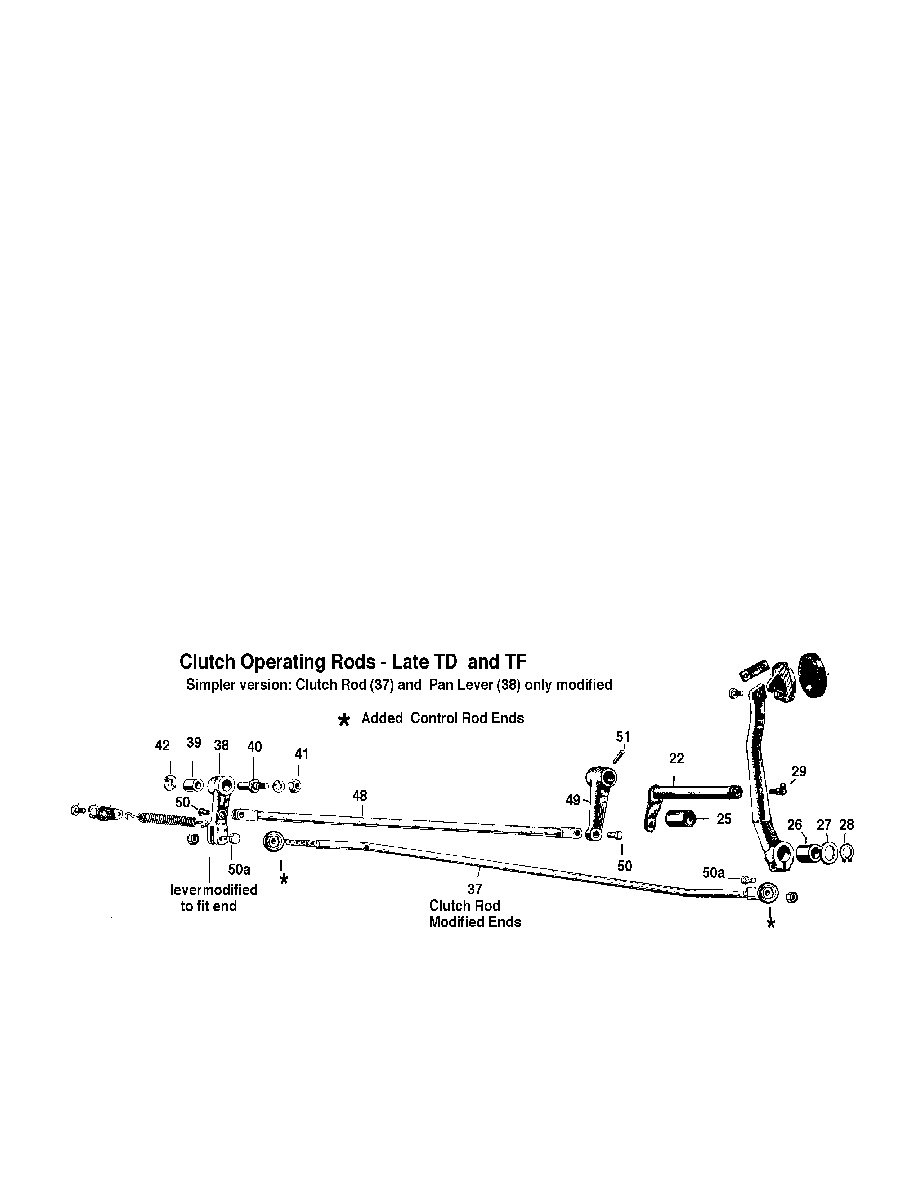
At control rod ends use bolts not clevis pins for the attachment (50a in drawing below are bolts instead of clevis pins (50).)
A simpler alternate version puts control rod ends on each end of the Clutch Rod (37) only, with a bolt thru pedal shaft
clevis pin hole, or add a clevis style “U”.to the lever on the pedal shaft. The Pedal shaft can then be unaltered, or perhaps
its lever is bent to give clearance between the rod end and the brake pedal.
In the simpler alternate, the original oil pan lever (36) and the Clutch Link rod (48) (the upper rod in sketch) could be
used, instead of the one shown, as this rod always moves perpendicular to its end pivots and control rod ends are not
essential here (Still put in Oilite bushings to lubricate the clevis pins).
Then modify the original oil pan lever (38) to accept the control rod end from Clutch Rod (37) in the the bottom yoke.
(The hole in (38) for the barrel pin needs filling in or bushed as it is too large for the bolt thru the control rod end).
Drawing of the Simpler Version
The hole in the front of the pedal box may have to be altered to clear the modified clutch rod (37)
A NOTE: My original system was made from the bearings, rods, and parts from a WW II surplus captured German Radar
set. The carefully engineered system used an incredible set of linkages to give the radar operator control of all the
systems of the radar. I was able to get all the components for my original system without modifying any of the parts used
except for the pedal shaft
. The version above can be made from the original rods or rods from the hardware store. The control rod ends are widely
used in race cars and are readily available from race car suppliers or bearing manufacturers.