Ttalk.info
Ttalk Tech
TD Anti Sway Bar System by Jim Merz
ANTI-SWAY BARS ON AN MG-TD
Original description by Jim Merz. See revised version following it.
After experiencing an undesirable roll on a curve that was banked the wrong way for water drainage on an Interstate Highway, I decided to stiffen up the front suspension. I noted in the two Moss catalogs (TD and MGB) that the rear A frame arms or Wishbone Arms carried the same part number. Working from that point, I bought the spring pans, front A frame arms, sway bar, links and attachments from a salvaged MGB. I found that the pans and front bars and pans are identical to the TD parts with the exception of the extra reinforcement and holes for the link attach points. I was going to disassemble the front suspension anyway to install V-8 bushings on the arms so it was not much additional work. With the front suspension reassembled, I worked from the new pans and arms by attaching the links to determine where the Sway Bar attachment brackets could fit. The front frame extensions were just where I needed them to attach the sway bar. With the Sway Bar attached to the links, I located and drilled the holes for the Bar brackets and bolted all in place. New rubber parts were used all around with the exception of the ends in the links which are not individually serviceable. You have to buy the whole link if you need new rubber in these parts. Besides, the links would be too expensive and can easily be replaced in the future if and when the time comes.
Initially, I had some concern about the strength of the frame extensions being able to support any torque from the Sway Bar. I thought I would try it with no doubler reinforcements on the inside of the extensions and see what would happen. After two seasons of driving, there is no indication that I need to add a reinforcement plate on each side.
I am very pleased with the way the car handles now. It will now go around that same reverse banked curve with no roll or feeling that the steering wants to "tuck in" and add additional pressure to increase the amount of turn you are applying with the steering wheel.
Revised description by Jim Merz, 12/12/2014
MG/TD Front Suspension
Modification
I was not happy with the “soft” front end suspension on my TD. Although I drive my car with care, it seemed that it could be improved and made a bit more responsive on curves, especially those that happen to be banked the wrong way on some roads. I decided to do something about it when I changed the front shock absorbers and added the MGB GT V-8 bushings.
By comparing the parts in a Moss MGB catalog with the counterparts of a TD, I figured certain parts would be interchangeable. I was right.
I bought the following parts from a salvaged MGB for my car:
5/8” Sway Bar
RH and LH Sway Bar Links
RH and LH Front Wishbone Arms
(2) Sway Bar Rubber
(2) Sway Bar Locators
(2) Spring Pans
I also bought the following new rubber parts:
(2) Sway Bar Rubber Mounts
(2) Sway Bar Bushings
As much as possible, I used original type TD Whitworth nuts and bolts in lieu of the SAE components used in an MGB. The rubber bushings in the sway bar links were serviceable and were reused.
All the used parts were cleaned and repainted to conform to the appearance of the other parts on my TD. I did not mention the fact that I had previously bought the V-8 bushings and other rubber parts used in the front suspension.
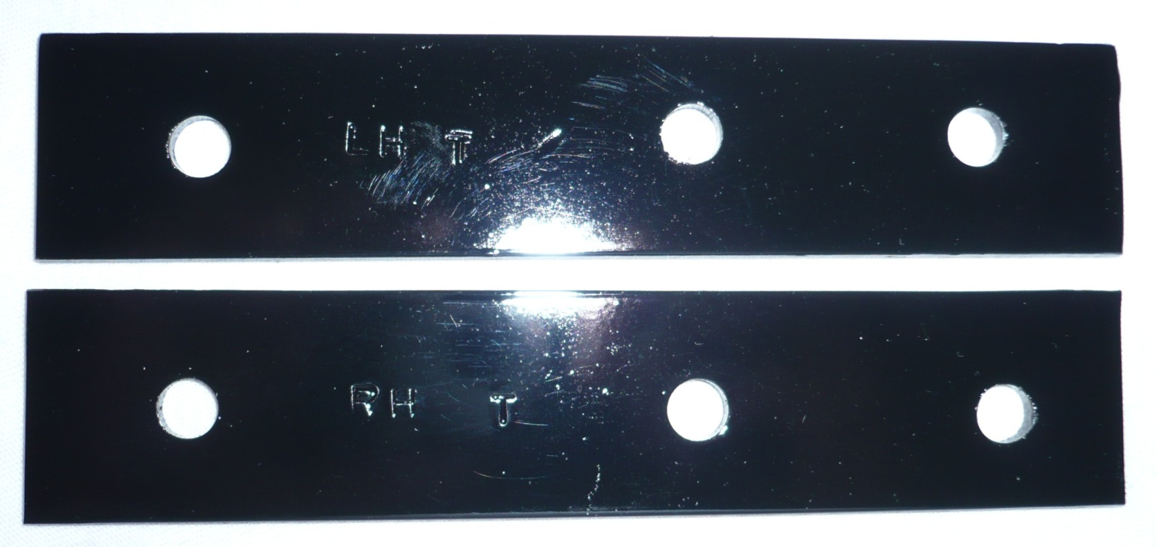
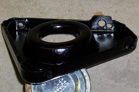
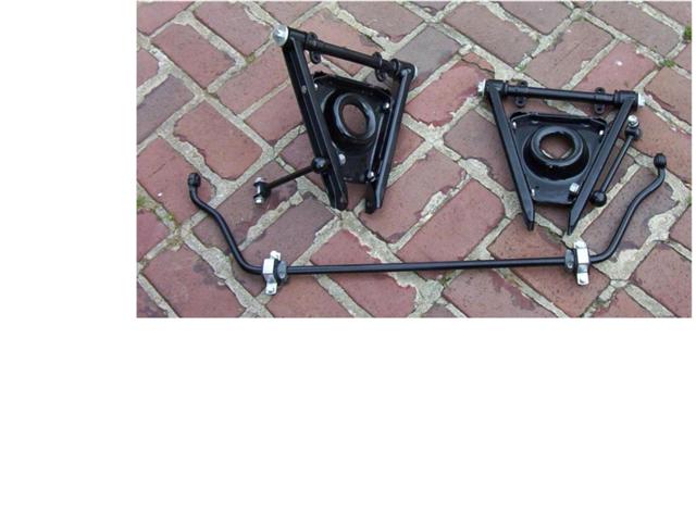
The pictures show the difference in the spring pans which have an added “ear” to accommodate the sway bar link. The wishbone arms are likewise strengthened with a reinforcement welded to the arm.
I used the normal factory recommended procedures to remove and reinstall the front suspension and shock absorbers and will not go into all those details at this time. This information is readily available from a multitude of other publications and sources including the Service Manual.
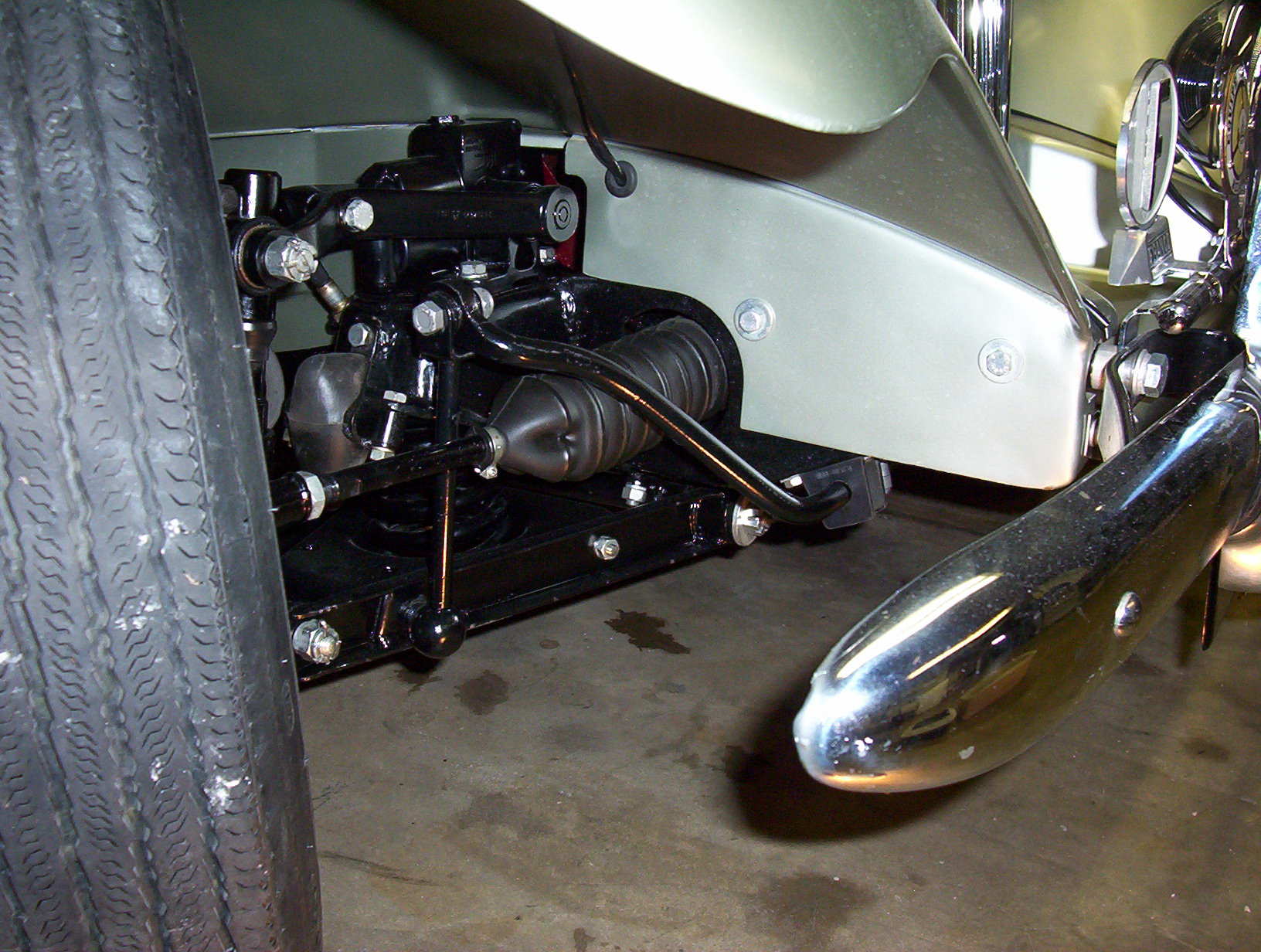
After the suspension components were installed, less the sway bar and mounting brackets, I mounted the sway bar to the links. I assembled the rubber mounting brackets with the rubber mounts to the frame horn extension or “dumb iron” as I have heard it called, and held the bracket with a clamp to the frame in order to locate and drill the first mounting hole for each bracket. I repeated this procedure for the other side. Then I bolted the brackets, rubber mounts and sway bar up in place to locate and drill a second bolt hole for each bracket. I considered making a 1/4” thick steel doubler for additional strength to be used on the inside edge of the frame extensions but decided to wait to see if it was needed. So far, I have found no bending of the frame horn flange where my sway bar brackets are mounted.
I have read where some owners shortened the sway bar link from the original MGB length but I could not see a need for this. Mine fits together very well and I chose not to modify any parts unless mandatory. There are rubber bushings in one end of the link and therefore can be expected to need replacement at some future time. Because of the orientation of the mounting points at each end, a jig would probably have to be used in the rewelding process. That just leads to unwanted potential problems. I kept it in the stock configuration.
The suspension on my TD feels very solid now and I am happy with the results of my effort. If I had to do it over again, I would do it!
Revision A
Subsequent to the initial installation, I found that the long vertical links from the MGB damaged the rubber gaiter on the right hand side causing an oil leak. I made a small jig to preserve the original orientation of the mounting studs after I cut and shortened the rods and had the pieces welded in their proper relative positions. There has been no damage to the gaiters with the shortened vertical links. In retrospect, I believe the contact between the two parts only occurred when I had the front end jacked up and the wheels turned to the fullest extent. Maybe the links didn’t have to be shortened but I prefer to be cautious.
Revision B
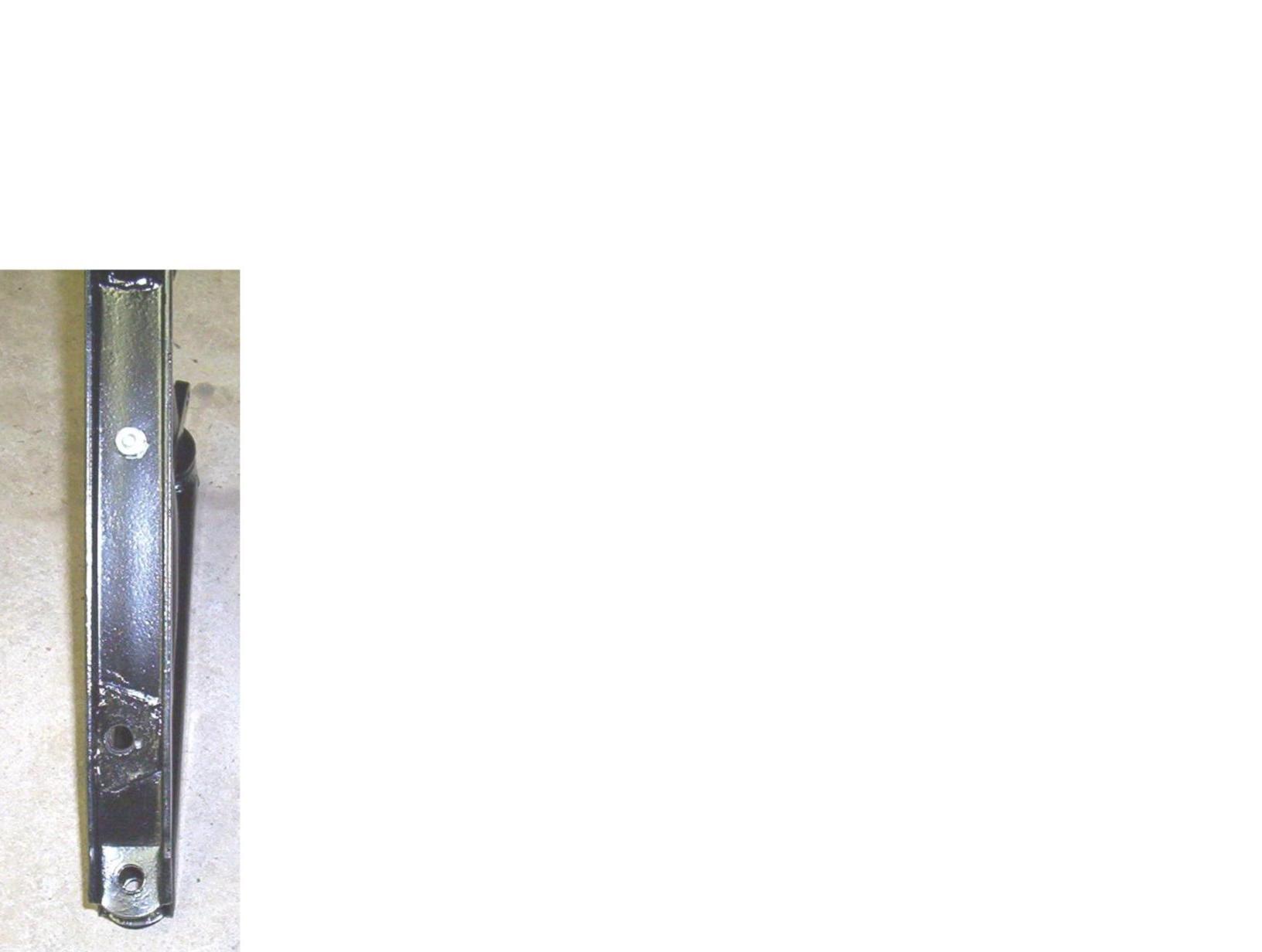
After several years of seasonal driving, I recently noticed a smile shaped crack in the paint on the lower flange of the right hand dumb iron just aft of the rear metal clamp that retains the sway bar. Inspection revealed a very slight upward bend in this flange. As I earlier wrote, I considered using a doubler to strengthen the flange but thought I would wait to see if it was necessary.
I have now fabricated and installed a doubler on each side to provide the additional strength that is required. The measurements for these parts are 6” x 1 ¼” x 1/8”. I believe that ¼” might be an overkill. We will see. The hole pattern is different for each side because the flange is narrower toward the front compared to the rear. They were backdrilled from existing holes on each side.