Ttalk.info
Pertronix Igniter Wiring
For Positive Ground Cars
The wiring diagram shown below was obtained from Pertronix to show the proper hookup for a Pertronix Igniter in a car wired for positive ground, or earth if you prefer. It goes without saying that this is valid only for cars without ballast resistors, viz., our T-series cars.
Correspondence from an engineer at Pertronix has given this insight into where folks run into problems, especially when installing the system into positive ground cars. He writes:
Bud,
Here is a diagram on the proper hook up. As long as people fellow the diagram it's really straight forward. Most of the problems happen when customers think we are wrong and proceeded to wire it in the way they feel is correct.
The instructions read something like this:1.Remove ignition switch wire from negative of coil terminal. Connect the black Ignitor™ directly to the ignition switch wire.
2.Connect the Ignitor™ black/white wire to negative side of coil. 3.Connect an insulated, AWG 20 copper stranded wire from the positive coil terminal to the positive battery or chassis. 4.The black/white Ignitor™ wire and the AWG20 copper wire should be the only wires connected to the coil.Here's the diagram:
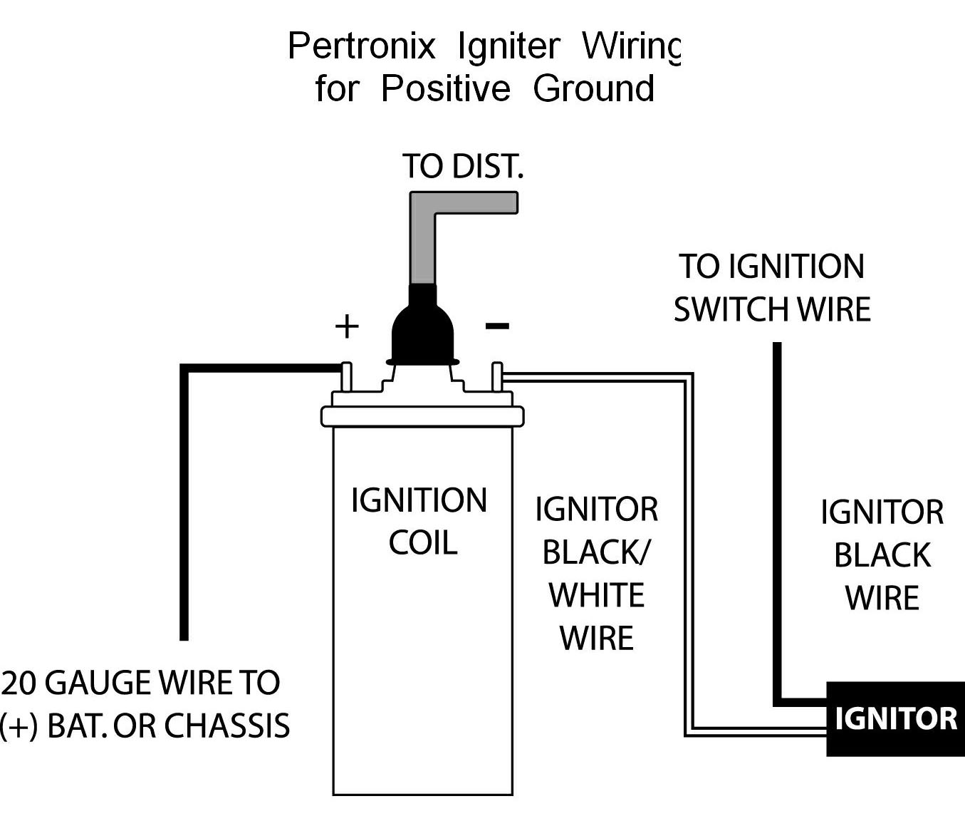
Probably the most significant thing to note is that the Pertronix Igniter module is connected between the coil and the ignition line, not between the coil and ground!
Procedures for testing a positive ground module are just a click away. Click here.