Ttalk.info
The Unavoidable Repair: Pedal Shaft and Bushing Replacement on TDs and TFs
by Jeffery Delk, Southeastern MG T Register
(Click here for original pdf file)
For our November Tech article, we reprinted Richard Kellogg’s excellent summary of how he repaired the TD/TF pedal shaft assemblies on left-hand-drive (LHD) cars (mgTalk: February, 1985). While the fundamental information in Richard’s article still remains very relevant today, many enthusiasts are now approaching the task in other ways and some minor aspects of the repair can be approached in a slightly different manner. Richard mentioned that his article was based on Bob De Costa’s earlier technical article (The Sacred Octagon: October, 1966), so the repair has been a topic of discussion (and frustration!) for some time. When preparing for our September Tech Session on Bill and Andria Dinzole’s LHD TD, I studied Richard’s article and reviewed various online questions/posts relating to pedal shaft repair. I want to thank Mr. De Costa and Richard for writing their earlier articles and extend thanks to those online who unknowingly provided additional information via their recent questions/postings.
Virtually every TD and TF on the road today has, at some point in its life, developed a lateral movement in the brake pedal. In some severe instances, this lateral movement may be accompanied by a fore-and-aft movement of the entire pedal shaft assembly (clutch pedal, brake pedal, and shaft). Any TD/TF driven regularly since the 1950s will have experienced repairs to this area at least once, if not twice, during its past 60 years of service. My TF had this problem when I purchased it, and I can assure you that the car did not inspire confidence when driving in either a normal or sporting mode! I had to hunt around with my feet for the pedals and then struggle to keep my feet on them once they were found. This is not an ideal situation for a sports car where shifting and braking are so fundamental to an enjoyable driving experience. After purchasing the car and making a list of the needed repairs, the brake/clutch pedal shaft and bushings sat high on the list. I couldn’t wait to get rid of the excess movement and restore the proper feel of the pedals.
The lateral movement of the brake pedal arm is caused by a worn pedal arm bushing – though wear in the actual shaft and the two in-frame bushings (inner and outer) will add to this movement. On LHD cars, the clutch arm is located on the shaft by means of a half-moon shaped Woodruff key and is secured to the shaft by means of a bolt, lock washer and nut – the bolt passing over a recessed area of the circular shaft. No interior bushing is fitted to the clutch pedal arm and, as a result, the clutch arm doesn’t suffer from the arm-to-shaft lateral movement that is so commonly found with the brake pedal/arm (see Figure 1). Any lateral or fore-and-aft movement of the clutch pedal arm is due (solely) to wear in the fit between the frame bushings and the shaft.
Over the years, many have expressed frustration about the "errors" that were committed during the original design of the pedal box and the pedal assembly (on both LHD and RHD assemblies). Some have questioned the logic of welding the pedal box to the frame and have suggested that a bolt-on box would have been preferable.
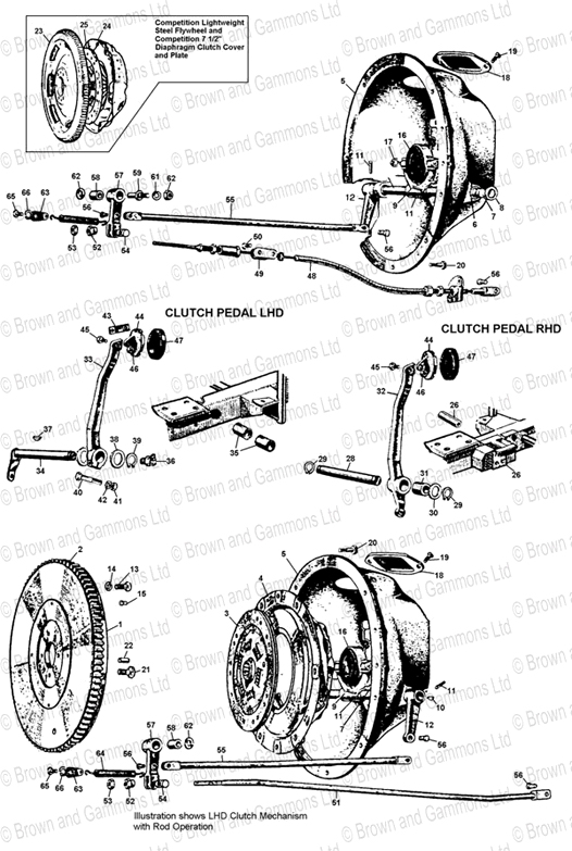
Fig. 1 Detail view of right and left hand pedal shaft assemblies – from Brown and Gammons parts list.
An indication of this frustration is that some boxes have been badly hacked up and cut away during earlier "repairs" (see Fig. 2).
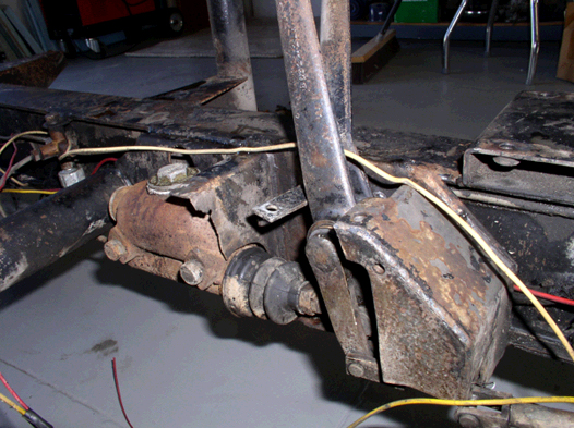
Fig.2 The remains of a pedal box that has been butchered during a previous "repair".
Others have suggested that the shaft’s grease zerk (where fitted) should have been placed on the interior end of the shaft (inside the pedal box) - as opposed to the exterior end (outside of the frame rail - where it is covered by the lower apron of the front fender). When the TD was designed, the pedal assembly arrangement found on MG’s existing Y Type Sedan was basically carried forward (with slight modification) for use on the TD. In retrospect, the arrangement seems to have had a limited service life – one that failed to see the car through its effective term of use. By 1953, Abingdon seems to have realized that the shafts were not holding up too well. One indication of this realization is that, on later cars, the shape of the front fender aprons was modified at the lower rear edge to facilitate service/repair of the pedal shaft. On the later TDs and all TFs, this modification allows for easy access to the shaft and its grease zerk.
A second indication was the introduction of a large, round service-access hole at the bottom of the pedal box – this allows for better access to the brake return spring and the ends of the pedal arms. Together, these two modifications make service and adjustment of pedal free-play much easier.
Almost everyone has criticized (with justification) the factory’s failure to make provisions for proper lubrication of the three bushings used in the pedal assembly and, over the years, the sole reason for most failures has been a simple lack of lubrication. One factor contributing to poor lubrication is the fact that the grease zerk location was never illustrated and was omitted from the lubrication charts found in the Nuffield-published TD/TF Operation Manuals and Workshop Manuals. The pedal shaft is referenced on page 45 of the TD Operation Manual and on page 40 of the TF/TF1500 Operation Manual – both references are found in the "Periodical Attention" sections. Under the heading "Every 500 miles (800 km.)", the manual outlines grease nipple locations and states "(On LHD models there is one on the clutch and brake shaft in addition.)". Unfortunately, they fail to mention that the grease zerk is hidden by the fender apron! Though mentioned in the text of these two Operation Manuals and possibly listed as "Lever Fulcrums" under section D of the "Key To Recommended Lubricants" chart, the pedal shaft grease zerk is not included in the accompanying two-color "Lubrication Chart" or the lubrication schedule found at the end of the Operation Manuals.
The factory Workshop Manuals for the TD and TF repeat this error. On page 15, the Workshop Manual carries the entry (mentioned above) under the heading "Maintenance Attention" – it later mentions the pedal shaft under Section P.4 (Item 6) on page P5. The entry is unfortunately omitted on the "Lubrication Chart", its accompanying listing of required lubricants, and the lubrication schedule. Note: The RHD shafts were not actually drilled for a grease fitting and did not (theoretically) require maintenance or mention in the original schedule – even though two bushings are used in that assembly (see notes below on the RHD assembly). The end result is that most pedal shaft assemblies were in service for thousands and thousands of miles without ever being greased – I doubt if any were greased every 500 miles as specified in the manuals.
A more significant factor contributing to the lack of lubrication is the factory’s provision of only two grease outlets for the shaft and bushings – when three (or more) outlets are actually needed for proper lubrication of the outer frame bushing, the inner frame bushing, and the brake pedal arm bushing. This oversight is even more apparent on the RHD cars – where there was no provision at all for greasing the bushings. This is especially bad as both the clutch and brake pedal arms rotate on a stationary shaft in the RHD cars. These poor design choices are the root problems and they are difficult to understand – even when one considers the low-cost approach to manufacture that was taken by Nuffield and MG at that time. I can’t imagine that an additional grease outlet hole for the inner frame bushing on the LHD shaft (and the drilling of the RHD shaft to provide for two outlet holes as well as the addition of a grease fitting) would have been that expensive. The end result of all of this is that the above factors combine to present current owners with sloppy pedals and an unavoidable repair.
Removal and Disassembly
Others are correct in stating that the pedal assembly is best repaired when conducting a complete restoration – when the body tub has been removed. This certainly makes things easier. That being said, it is still relatively easy to remove and replace the shaft and bushings with the car intact. Neither the left-hand floorboard nor the gearbox were removed for the last two shafts I have replaced (LHD TF1500 and LHD TD). It is a tight squeeze – but it can be done. For the Dinzole’s TD, we did remove the left front fender – to give access to the exterior end of the pedal shaft. Even this is not necessary when working on the later TDs and all TFs.
If you take a minute and perform a quick Google search on the web, you will find several technical entries and BBS discussions relating to the "pedal box" and "brake/clutch shaft replacement". Most begin by saying that the repair is "the worst job you will ever do on your T car". While the job is messy and somewhat involved, my experience (and that of others) has shown that it is really not that difficult. It is probably one of the most rewarding repairs you can make on your car. It can be done in a day with ease and the repair will transform your driving experience. For the money, it is one of the best things you can do to restore the car’s responsive nature when driving.
As our goal on the Dinzole’s TD was to remove and replace the shaft and bushings in one morning session – with other Club members watching - we pre-ordered the shaft, the two frame bushings, the brake pedal arm bushing, the two spacers, a circlip, and one grease fitting. You may wish to order new brake and clutch pedal pad rubbers, a new fume excluder and retainer, clutch and brake arm clevis pins, and a brake return spring, if these items are needed. Many have commented that the brake return springs being supplied are not correct for the cars. I had this experience with the spring I ordered – in the resting position, the spring hangs loose and does nothing to help pull back the pedal arm. Many simply run the cars without a return spring as the fume excluder rubber pulls the arm back on its own.
Step 1: As soon as possible, begin to soak the clutch/pedal shaft joint with PB Blaster, Liquid Wrench, or some other proper penetrant (do not use WD 40 as it is a lubricant and is not really intended for use in releasing a rust bond). Repeat this several times before you begin your repair. One of the most frustrating aspects of the repair – one that can sneak up on you and cause some difficulty – is the removal and replacement of the clutch pedal arm. A rust bond can sometimes form between the clutch arm and the pedal shaft. If the arm is rusted to the shaft, it will be very difficult to separate the two and remove the assembly from the small opening in the side of the pedal box. Once the shaft has been driven out of the two frame bushings, the entire assembly will be flopping around loose inside the pedal box – with the upper ends of the two arms sticking up through the floor board opening and the clutch arm and the lower ends of the pedal arms sticking down inside the box. It is difficult to separate the clutch arm from the shaft once you reach this point. Some enthusiasts have reported great difficulties with this – so start spraying in advance of your repair. You will need to remove both pedal pads and the rubber fume excluder to gain access to the top of the pedal shaft assembly.
Step 2: Order your needed repair parts – go ahead and order a new pedal shaft as yours will most likely be worn. Some owners, those with the skill and the proper machine tools, have refurbished old shafts by building them up (the shaft surface) by welding, and then turning them back down to the original specs. This is beyond the skill level of most owners. A local machine shop may be willing to do this for you, but I would look into the cost and compare it to that of a new shaft. You will also need two bushings for the frame, one bushing for the brake pedal arm, a circlip, a grease zerk, and two clevis pins.
Step 3: Remove the side cover (remove the three bolts/lock washers and the one nut/washer). Having three bolts and one stud is correct – as this allows the cover to be opened for normal servicing without actually removing it from the box. Once removed, you will notice that the pedal box opening has a small relief cut into the center of the lower flange/lip – this relief allows the lower end of the clutch arm to pass in and out of the box during the removal and replacement of the shaft. The arm must be correctly rotated/positioned to pass through this opening. Be mindful of this later as you drive out and then replace the shaft. Remove the clevis pins from the brake and clutch pedal arms and remove the brake return spring (if one is still fitted). I find it helps to remove the brake master cylinder as this gives you a little more room inside the box for cleaning and allows for easier manipulation of the pedal assembly - this is not required however. Remove the clevis pins from the ends of the brake and clutch arms. Remove the clutch linkage (cable or rod) from the box. Remove the nut, split washer and pinch bolt from the clutch pedal arm.
Step 4: Remove the circlip from the external end of the pedal shaft. If you are working on an early TD, you will need to remove the left front fender in order to gain access to the circlip and shaft. Remove the grease zerk fitted to the end of the shaft. Using a drift, drive the shaft into the frame – be sure to avoid hitting the bushing as you do this. The shaft should move with ease as everything will be quite worn. The shaft will stop once the pedal arms have stopped against the interior of the box. From above, tap the clutch arm back to the left to expose the Woodruff key. Brace the pedal shaft in position by bracing the clutch drop arm as you tap back on clutch pedal arm. Remove the key with side cutters or wire cutters – the tight fit of the key makes it almost impossible to remove the key from above with needle-nose pliers. With the key removed, the clutch and brake arms can be moved off of the shaft as you finish removing it from the frame. You may need to twist it as you pull or tap it out. Watch for the spacers on both sides of the brake arm. The two frame bushings may now be removed. These are driven out of the frame with either a shouldered mandrel or a suitable socket and extension. Drive the outer bushing into the frame to make contact with the interior bushing – keep tapping until both drop into the pedal box. Others have used pullers to remove and refit the bushings. Some bushings may simply pull out with your fingers as they have worn to such an extent to be non-functioning. After driving out the two frame bushings, make certain that the bushing tube is free from nicks and other deformities. A nick or a gouge can cause the new bushings to seize in an improper position or become cocked as they are first introduced into the tube.
Step 5: With the space now empty, this is a good time to face the 60 years of collected goo that you will find in your pedal box. Grease, sand grit, old split pins, bolts, washers, you name it – all may be found in the box. As you excavate all of this from the box, just scrape it off on an old shop rag or some paper towels – have an entire roll on hand as this is the messy part. Keep digging this goo out until the interior of the box is nice and clean. I complete the cleaning by wiping everything down on the inside with carb cleaner that had been sprayed into a clean shop rag.
The early pedal box, as found on TDs prior to Nov. 1952 (TD 22251), lacks the clutch stop that is on later cars (see Fig. 3).
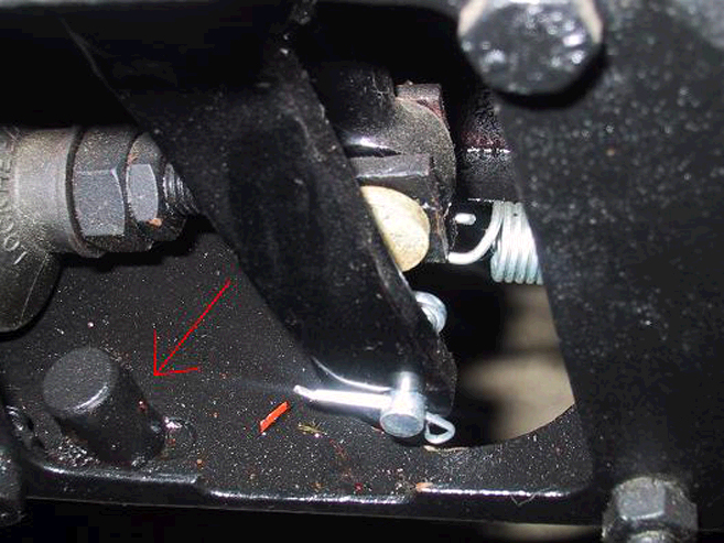
Fig. 3 View inside the pedal box showing the stop-pin for the clutch, the recessed area at the base of the inspection cover opening (to allow for the passage of the clutch lever arm, and large, round opening found at the bottom of the later-style pedal box (as fitted to later TDs and all TFs).
This clutch stop was fitted at the same time the rod operated clutch replaced the cable operated clutch. The placement of this stop pin prevents the arm from moving too far back, bending the clutch actuating rod, and over extending/stressing the clutch release fingers. If your pedal box has a small hole in the bottom – you are most likely missing your clutch stop pin. The early pedal box also lacks the large round access hole that is found in the bottom of the box on later TDs and all TFs. This large opening greatly aids access and simplifies maintenance and repair. Neither Moss nor Abingdon list a cover plug for this access hole – though a suitable rubber plug with a lipped flange (similar to that found on the later type master cylinder inspection hole) may be used to seal off the opening.
This is a good time to check the clevis pins for wear – replace these if needed as this will remove some of the lost motion that may exist in the clutch and brake linkages (see Fig. 4).
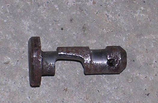
Fig. 4 Example of extreme wear on a pedal arm clevis pin.
Also check the clevis pin openings in the pedal arms – if worn, consider welding them up and redrilling for a better fit. The lost motion at the lower end of the arm is greatly magnified as you move up the arm to the actual pedal – so that minimal movement at the base of the pedal arm will actually feel like a great deal of lost movement when placing your foot on the pedal pad during use.
Modification of the Pedal Shaft
After receiving the new replacement shaft, I took it (and a copy of Richard’s tech article) to my local machine shop with the request that they modify the shaft by drilling extra lubrication holes and cutting the three lubrication grooves. I decided to have them drill completely through the shaft for each of the three lubrication points – for a total of six lubrication exit points. Once all holes were drilled, the lubrication grooves were cut – one groove for each of the three sets of lubrication holes (see Fig. 5 and 6). This machine work cost $30 dollars and I consider it money well spent. The six grease holes feature chamfered edges and these aid in distributing the grease once the bushings are in place over the exit holes in the shaft. When I tested the complete assembly on the workbench, I confirmed that, when pressured in by the grease gun, the grease would travel completely around all grooves and would spread out under the surface of each bushing. The tolerances are such that grease would travel to the absolute edge of the bushings. The pumping in of the grease filled the slight bit of clearance between the bushings and the shaft. This made for a very snug fit – just what we are after! With use, I think the coverage will be more than adequate. Richard’s article mentions the cross hatch design for the lubrication grooves. I agree that this is the preferred pattern – as it promotes better surface coverage, see Figure 7. I went with the simple grooves as these were easily cut by the machine shop and I had only one afternoon to modify the shaft before installation.
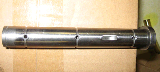
Fig. 5 Modified shaft for LHD TD/TF: showing the three lubrication grooves and the three upper lubrication holes. The slot for the clutch arm’s Woodruff key is shown between the upper lubrication holes for the inner frame bushing and the brake arm bushing.
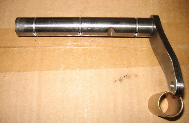
Fig. 6 Modified shaft for LHD TD/TF: showing the three lubrication grooves, the three lower lubrication holes, and the drop arm for the clutch linkage. The clearance recess for the clutch arm pinch bolt is visible between the lubrication holes for the inner frame bushing and brake arm bushing.
Reassembly
Reassembly is rather straightforward. Take a moment to completely assemble the pedal shaft and arms on your workbench before refitting the assembly inside the box. This will ensure that everything will align properly and will help you envision how the various components must be sequenced when working inside the pedal box.
When refitting, the new shaft should be held halfway into the pedal box and the pieces positioned back onto the shaft – spacer washer, brake pedal arm, spacer washer, Woodruff key then clutch pedal arm. I find that it is best to have a helper hold the assembly from underneath as you refit the Woodruff key from above. With the floorboards and gearbox in place, there is very little room for this procedure. The assembly will be located into the interior frame bushing as the clutch pedal arm is pushed into position over the Woodruff key and on into the proper position on the shaft. Lightly sanding down the woodruff key is essential when refitting the clutch arm. I lightly sanded the key on wet 1000 grit sandpaper until I had an easy hand-press fit to the shaft. Spreading apart the clutch arm end was also most helpful – it only takes a slight tap or two with a small machine hammer on a chisel to gently spread the split halves of the clutch arm – this greatly eases the fit when sliding the arm off and back over the shaft and the woodruff key. The bolt, washer, and nut can then be refitted and used to draw the two halves back tight against the shaft – thus clamping over the key. The slight spreading of the arm halves doesn’t interfere with the alignment of the two bolt holes.
Once all components are on the shaft, continue pushing the shaft into the frame and the outer frame bushing. When everything is pushed home, replace the clutch arm’s bolt, lock washer, and nut and tighten. Replace the circlip and install the grease fitting at the exterior end of the shaft. You may be able to feel a very slight side to side (lateral) movement of the shaft once everything is in place and locked down with the circlip. Once all the grease is pumped in, this movement will decrease. Replace the clutch and brake linkages and fit the new clevis pins. Be sure to confirm the free correct free-play for both linkages:
(brake: 1/2 inch; clutch: 3/4 inch) when replacing.When refitting the pedal box side cover, take a moment to make a cork gasket for this opening. It seems that these gaskets were fitted originally – though most are missing as they all seem to have been discarded over the years during the course of earlier repairs/service. There will be a small gap between the cover and the side of the box if no gasket is fitted. Now that your pedal box is nice and clean, you want to keep it that way by using one.
Replacement Part Variations
The bushing for the brake pedal arm was found to be slightly too wide for the pedal arm – when installing this bushing, I simply centered it so that the extra width was evenly distributed on each side of the pedal arm, opening. This extra width did not interfere with the fit of the clutch and brake pedal arms, the distance pieces, or the circlip.
Others have reported that the distance washers now being supplied are slightly thicker than the originals. I found this to be true with the two washers purchased for the Dinzole’s TD. It may be that Moss is attempting to help take up some of the slop by providing slightly over-sized distance pieces here. The washers supplied were actually formed by joining together two thinner washers. On this repair, we opted to reassemble with the original distance washers. The replacements had been ordered before hand – in the event the originals were missing.
There was one report online of an owner who completed the repair – only to find that his pedal box inspection panel/cover would no longer fit over clutch arm and the side opening. It was determined that the replacement shaft assembly was welded up with a clutch actuating arm that was bent incorrectly and was too thick. We did not encounter any problems with the Moss-supplied replacement pedal shaft. Careful attention to the assembly order will also help you avoid any unpleasant surprises as an incorrect placement of the two spacers will cause problems on reassembly.
Right Hand Drive TDs & TFs
For those with right hand drive TDs and TFs, the brake/clutch pedal shaft assembly is less complex. The pedal shaft is a plain, simple shaft – with no drop arm welded on the inboard end for the clutch linkage. The assembly uses only one spacer washer, two circlips, and two pedal arm bushings. Both the brake and clutch pedal arms rotate on the shaft – which remains stationary within the frame. Since there is no need for this shaft to rotate, no bushings are fitted to the frame for the right-hand-drive pedal shaft. The problem most often encountered when repairing the right-hand-drive assemblies is that the shaft becomes fused to the inside of the frame by a coating of surface rust. The shaft must then be heated/cooled and pounded out of the frame – not an enjoyable exercise. As with the LHD shafts, the RHD shaft should be modified to incorporate an interior grease passage, a grease zerk, and two (or four) grease outlets with appropriate connecting grooves under the clutch and brake pedal arm bushings. See Figure 7. Unlike LHD, RHD owners do not have to fight the buildup of grease in the pedal box, since none was ever used!
The fender will have to be modified on early TDs to allow access to the grease fitting, see Figure 8..
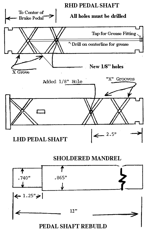
Fig. 7 Kellogg’s Drawing with RHD Shaft added
mgTalk, Vol. 11, No. 2, February 1985
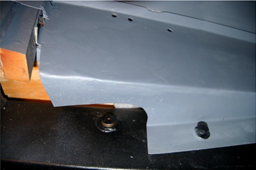
Fig.8 Fender Cutout to allow access to grease fitting on RHD MG TD and TF
Conclusion
Don’t be afraid of peering into your pedal box and making this repair. Whether pleasant or unpleasant, your personal experience with the repair will most likely be a once-in-a-lifetime experience (unless you kindly offer to help others!). If repaired properly, you will never have to deal with the assembly again – unless you are performing a routine adjustment or greasing the shaft and those new bushings. Once you have finished, I doubt you will ever forget where that grease fitting is located – and you will be able to enjoy once again (or for the very first time) driving your MG like an MG - not a bad trade off in my book!
When purchasing some bearings a few months ago, I looked into the possibility of using the new, low-profile needle bearings as substitutes for the bushings found in the brake pedal arm and the two in-frame bushings. Don Harmer made this substitution years ago – so it is possible. I have contacted a local bearing supply house and am attempting to identify direct replacements. The wide needle bearings would be a welcome modification – if the proper sizes can be sourced. If you have part numbers for substitute needle bearings, please let me know.
Jeffrey DelkRight Hand Drive was edited by Don S.Harmer
mgTalk. Vol. 37, No. 1, January 2011
The Southeastern MG T Register
New details about modifying an RHD Pedal Shaft, courtesy of Rod Jones. Click here on PedalShaftRHD

email to:Bud@Ttalk.info