(Images are thumbnails, click to expand them)
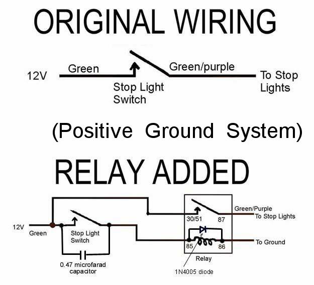
I've elected to add a relay to my TD's brake light system. The wisdom of adding a relay to the brake light system is covered very well in an excellent article by David DuBois that can be seen at http://www.omgtr.ca/technical/brakelightrelay/brakelightrelay.htm. In fact, with Dave's permission, I'm going to use some of his material in this page. I am not advocating that viewers should do what I've done, I just thought that some may be interested in seeing how I did it.
It cost me about $10US for the parts and I probably could do the job now in about half an hour. Here's Dave's drawing of what I intended to accomplish:

 And, here's what
I used to do it (plus an electric drill).
And, here's what
I used to do it (plus an electric drill).
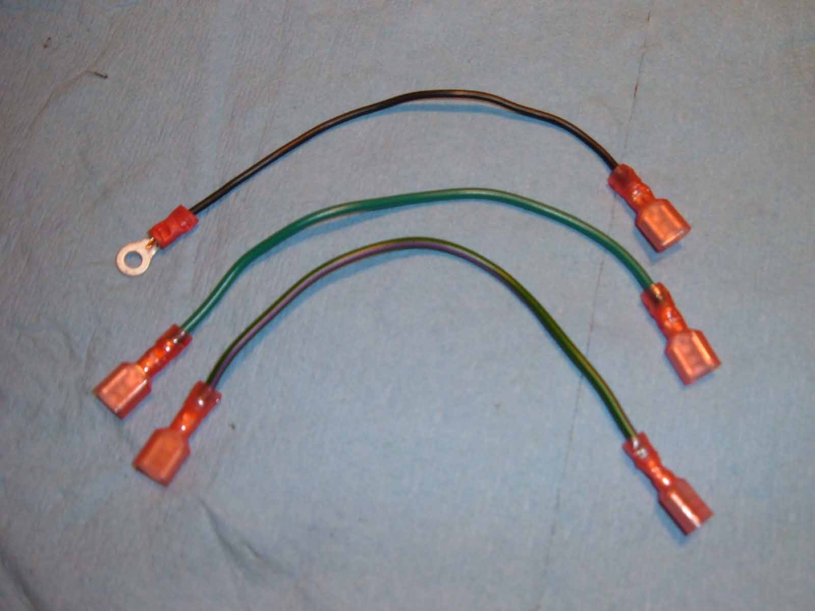
3 jumper wires are necessary. On the order of 7" seems about right.
One is a black ground wire with a ring connector on one end and a female
spade on the other. Another is a green wire with spades on each end
for the 12 volt line. The third is a piece of green/purple wire with spades
on each end. Obviously, the color codes don't have to be followed, but
it makes me feel better.
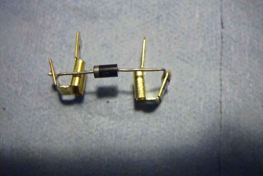 Though
I didn't opt to add the capacitor across the switch contacts, I
Though
I didn't opt to add the capacitor across the switch contacts, I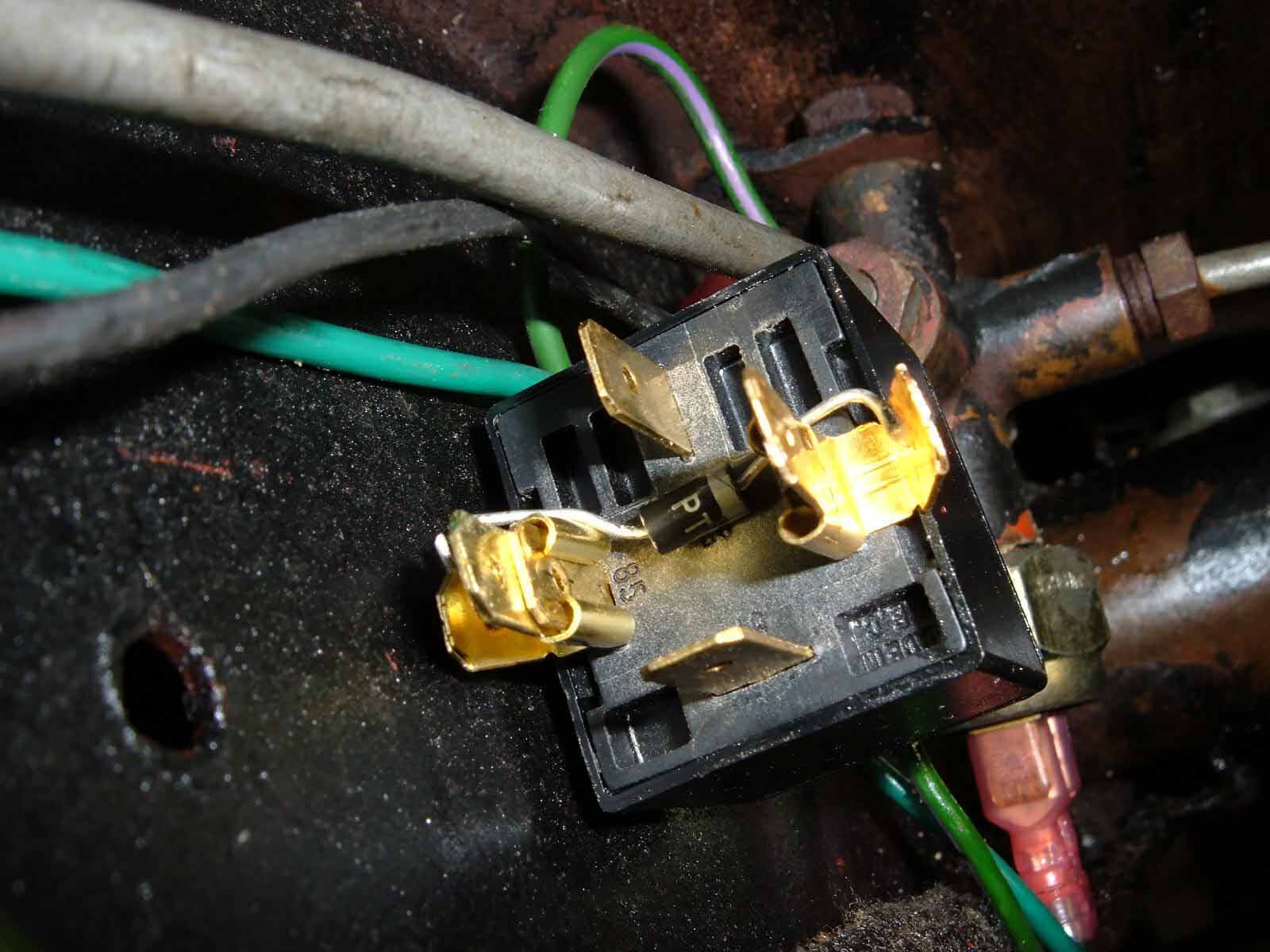 did add the diode across the relay coil. This added two more
'piggyback spade connectors', plus the diode. I soldered the diode
between two piggyback connectors. Conveniently, this allows the diode
to be easily reversed for negative/positive grounds.
did add the diode across the relay coil. This added two more
'piggyback spade connectors', plus the diode. I soldered the diode
between two piggyback connectors. Conveniently, this allows the diode
to be easily reversed for negative/positive grounds.
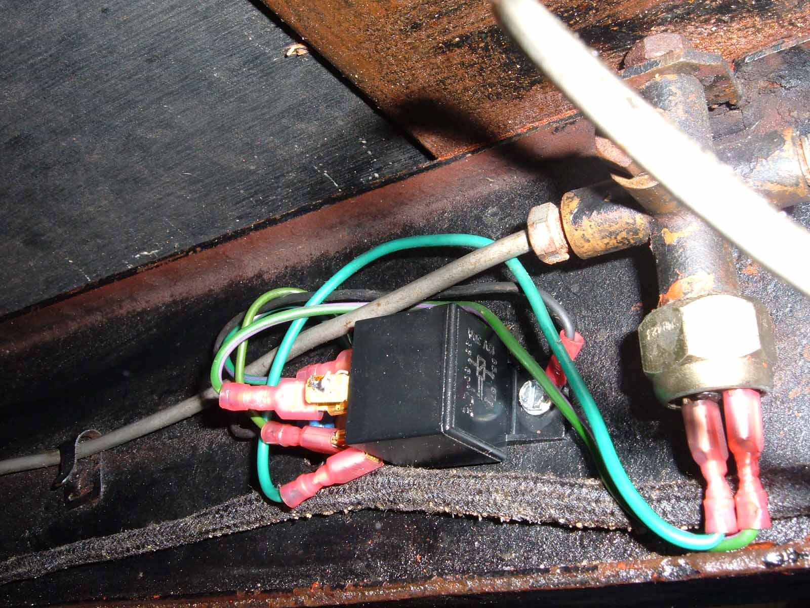
Next step was to get under the car with a drill. I
drilled a small hole in the left frame member approximately an inch toward
the rear from the four-way hydraulic connector into which the brake light
switch is inserted. This shows the mounting of the relay using a sheet metal
screw through the hole. This screw was also used as the source of
ground, note the black wire with its ring terminal under the screw head.
The other end of the black wire goes to the free half of the piggyback onto
which the diode is mounted (#85).
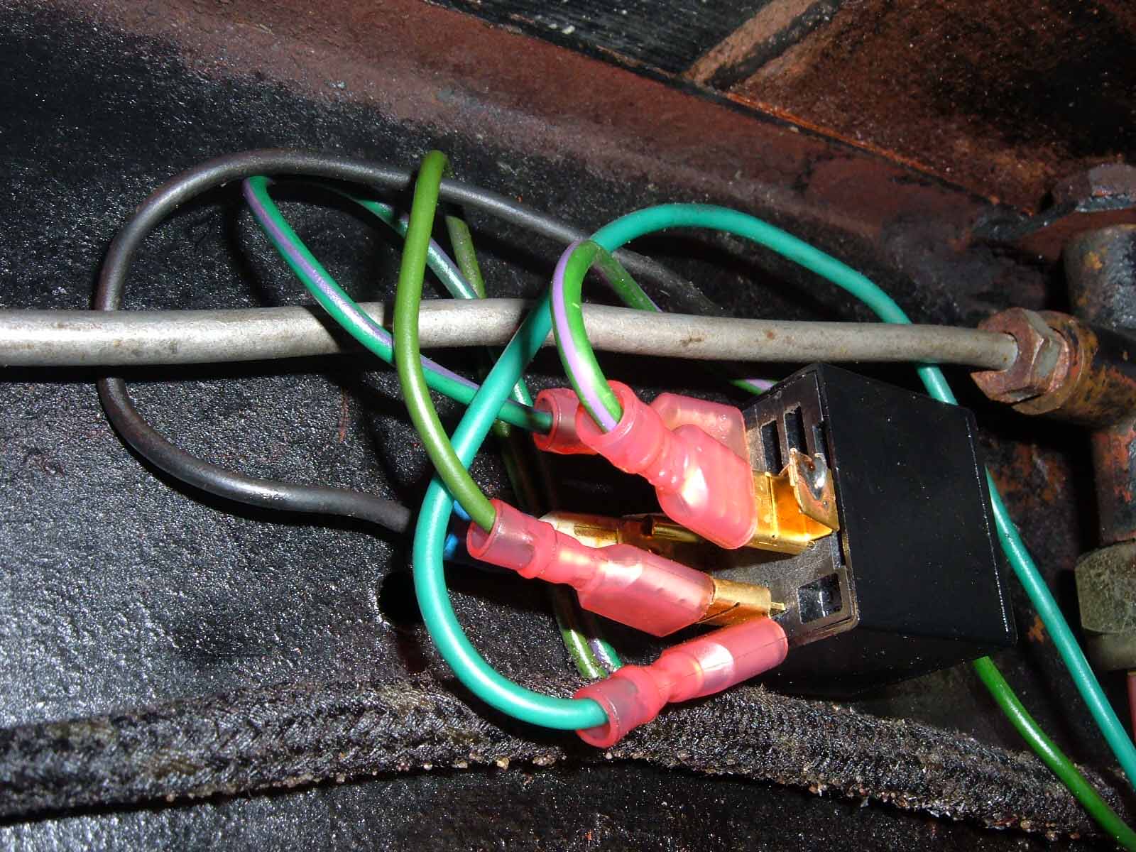 Then
it's just a matter of connecting the wires up to the correct terminals.
You might note that the green wire from the harness goes to one side of the
piggyback attached to the bottom relay terminal (#87) and the green/purple from
the harness is attached to the upper terminal (#30/51). I found it more
convenient to wire it this way to avoid the brake line. The green jumper
wire is then connected between the other half of the lower piggyback to one side
of the brake light switch. The green/purple jumper wire is the connected
between the other side of the brake light switch and the free half of the
piggyback connector attached to the ungrounded end of the diode (#86).
Then
it's just a matter of connecting the wires up to the correct terminals.
You might note that the green wire from the harness goes to one side of the
piggyback attached to the bottom relay terminal (#87) and the green/purple from
the harness is attached to the upper terminal (#30/51). I found it more
convenient to wire it this way to avoid the brake line. The green jumper
wire is then connected between the other half of the lower piggyback to one side
of the brake light switch. The green/purple jumper wire is the connected
between the other side of the brake light switch and the free half of the
piggyback connector attached to the ungrounded end of the diode (#86).
That's all there is to it! Time will tell how well it holds up, but I think it'll be fine. If my brake light switch had been of the type that used grub screws instead of spade connectors it wouldn't have added any complication. I would have just taken the spade connectors that were going onto one end of the green and green/purple jumpers and put them onto the wires that I took off of the brake light switch.
BTW, I've also added a pair of removable high-mount lamps to the top of the fuel tank. This has doubled the brake light current. The removable high-mount lamps weren't very difficult to do, required zero modifications to the TD, are easily removed and only cost about $50US to install. I hope to have that page added very shortly, look for High-Mount Lamps in the Tech Index. It's there.

email to:Bud@ttalk.info
created September 16, 2005