from
DynamatorInnards Images taken by Jim Northrup while disassembling Dynamator from
Mort Resnicoff. Images are thumbnails, click on image to enlarge it
Ttalk.info
Innards1
 0002.jpg
Depicted are the rotor with its field windings, one of the two
bearings, two copper slip rings to conduct the DC field current into
the field, the integrated voltage regulator with brush holder and
spring loaded carbon/graphite brushes and the rear bracket. The red
wire from the rear bracket is the regulator's negative lead. The
red wire with the spade terminal is attached to the rectifier
positive and provides the juice to the regulator once it starts
charging. The wire to the F terminal on the side of the housing
hooks to the IGN LAMP so the field gets a trickle of electricity
before alternator starts running. Both negative and positive ground
alternators probably use the same regulator. Here's the issue with
the positive ground cars, the regulator needs positive feed, and
the IGN LAMP is negative. That's why the positive ground
alternators need the relay, to switch the regulator to ground for
positive feed! Whatever works!
0002.jpg
Depicted are the rotor with its field windings, one of the two
bearings, two copper slip rings to conduct the DC field current into
the field, the integrated voltage regulator with brush holder and
spring loaded carbon/graphite brushes and the rear bracket. The red
wire from the rear bracket is the regulator's negative lead. The
red wire with the spade terminal is attached to the rectifier
positive and provides the juice to the regulator once it starts
charging. The wire to the F terminal on the side of the housing
hooks to the IGN LAMP so the field gets a trickle of electricity
before alternator starts running. Both negative and positive ground
alternators probably use the same regulator. Here's the issue with
the positive ground cars, the regulator needs positive feed, and
the IGN LAMP is negative. That's why the positive ground
alternators need the relay, to switch the regulator to ground for
positive feed! Whatever works!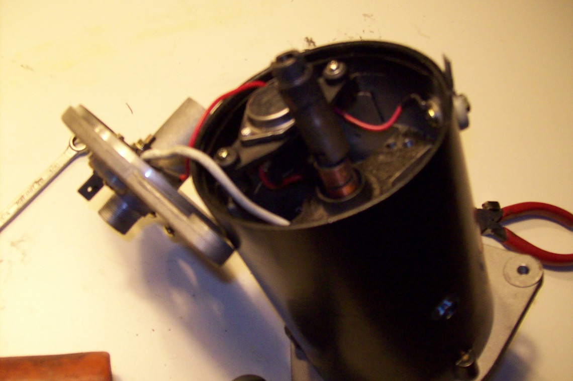 000_0003.jpg
Partial assembly of regulator, stub shaft and rear bracket.
000_0003.jpg
Partial assembly of regulator, stub shaft and rear bracket.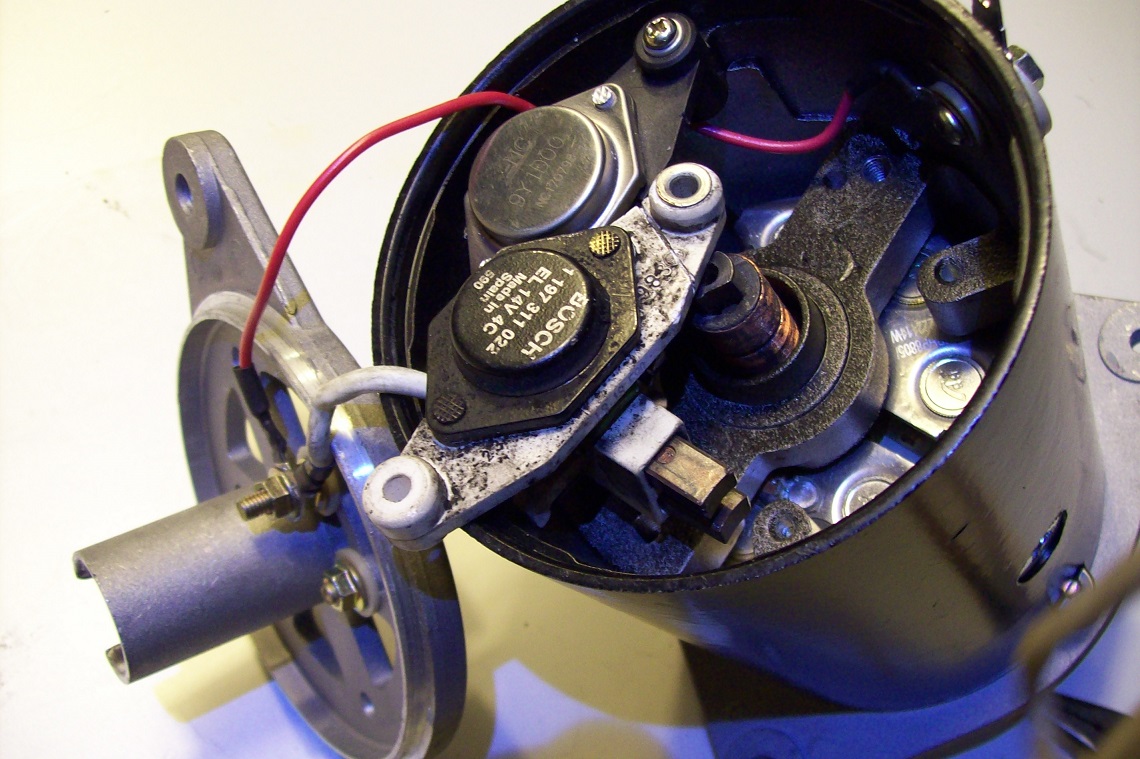 000_0002.jpg
I couldn't track down the origin of the Dynamator regulator, but
fear not, the white one came out of an early 1980s Mercedes
alternator so replacement parts can be had. Hopefully, the
Dynamators will last a quarter million miles like the Mercedes. A
Mercedes/aftermarket regulator would need the three wires soldered
on, not rocket science.
000_0002.jpg
I couldn't track down the origin of the Dynamator regulator, but
fear not, the white one came out of an early 1980s Mercedes
alternator so replacement parts can be had. Hopefully, the
Dynamators will last a quarter million miles like the Mercedes. A
Mercedes/aftermarket regulator would need the three wires soldered
on, not rocket science. 11.jpg
looking down the front of the housing, fixed stator windings laced
within the iron frame around the inside diameter are where the
electricity is produced. There are six wires from the three
separate phases of windings in stator soldered to leads on six power
diodes in the center. The six diodes are assembled as the
rectifier.
11.jpg
looking down the front of the housing, fixed stator windings laced
within the iron frame around the inside diameter are where the
electricity is produced. There are six wires from the three
separate phases of windings in stator soldered to leads on six power
diodes in the center. The six diodes are assembled as the
rectifier.